iSCSI with Jumbo Frames and Port Binding
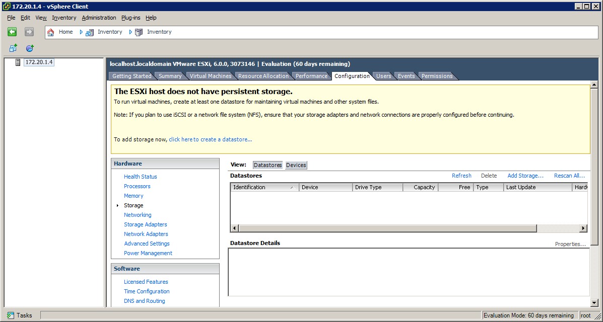
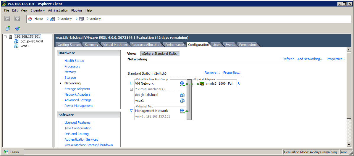
Immediately after installing an ESXi Server, you may or may not have any storage at all. Most ESXi servers today are diskless, with the ESXi installation living on some sort of flash-based storage. In this case a fresh installation of ESXi will present with no persistent storage whatsoever, as you can see in the example below:
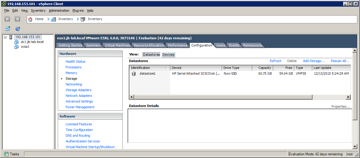
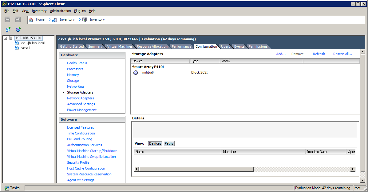
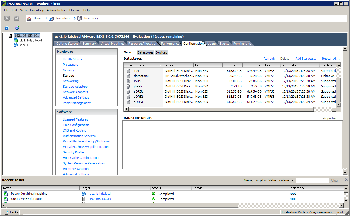
Some servers, however, still have traditional disks as in the screenshot below where clearly see the HP Serial Attached SCSI Disk, A.K.A. “Local Storage” or “Directly Attached Storage,” but no other storage is listed.
In either case, it should be noted that it is a Best Practice, when installing ESXi to disk or media, to use a RAID 1 configuration for the location of the ESXi installation.
iSCSI Storage Network Examples
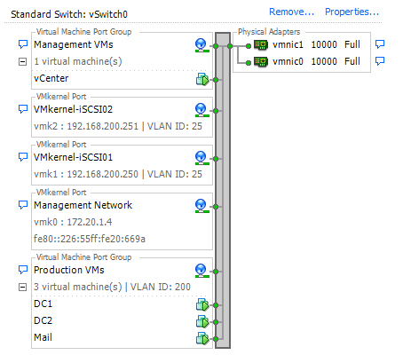
Our first task will be creating a network for iSCSI storage traffic. This should be a completely separate network from Production or Management networks, but how you create the separation is entirely up to you.
Most VMware admins will prefer a physically separate network, but in the days of 10Gb NICs and a relatively smaller number of interfaces[1], VLAN separation will work as well.

Configuring an iSCSI Network on dedicated NICs
Creating a network for iSCSI Storage
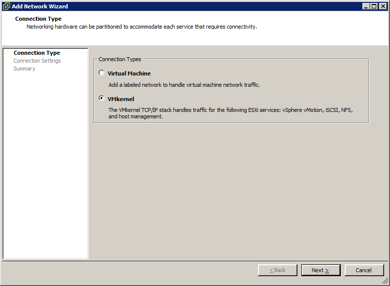
Let’s begin by adding an entirely new vSwitch for our iSCSI Network. Click on: Add Networking in the upper-right corner of the screen
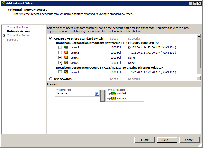
Select: VMkernel as the network type

Choose to create a vSphere Standard switch, using all of the interfaces which are connected to your iSCSI Storage network. In this example, vmnic4 and vmnic5 are connected to the iSCSI Storage network
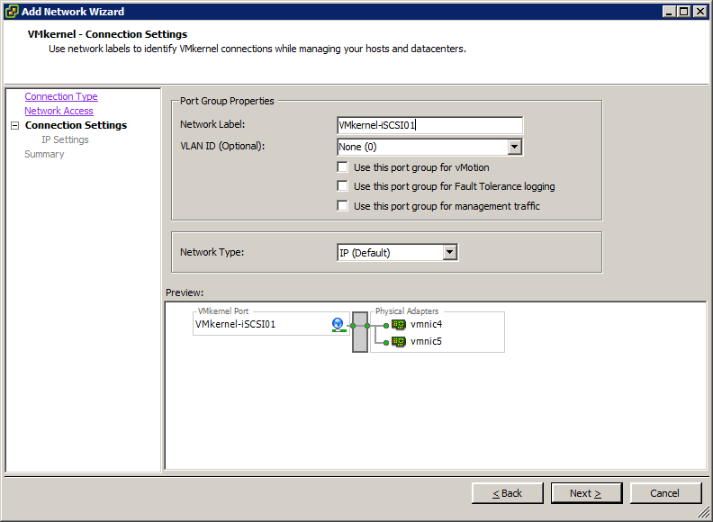
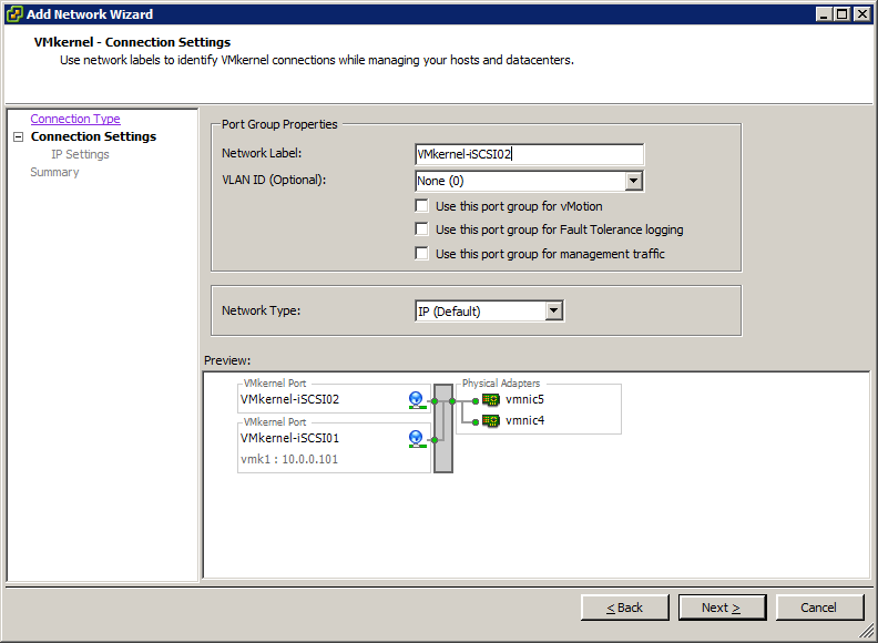
For the Network Label of your first VMkernel connection, choose a name that can be remembered sequentially. I always create my VMkernel connections for iSCSI in the following order:
- VMkernel-iSCSI01
- VMkernel-iSCSI02
- VMkernel-iSCSI03
- VMkernel-iSCSI04
If I have 2 physical uplinks (NICs), I will create 2 VMkernel connections for iSCSI. If I have 4 uplinks, I will create 4 VMkernel connections for iSCSI. Following this standard for your iSCSI configuration will conform with VMware requirements for Port Binding[2] and assist you in establishing the order in which you bind the VMkernel connections.
Set a VLAN ID, if that is appropriate for your environment
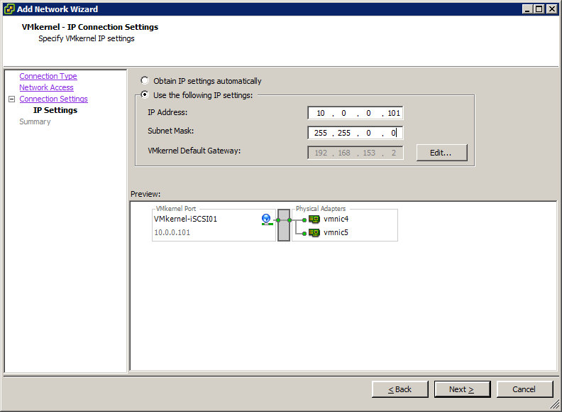
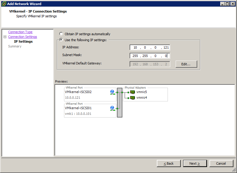
Now choose an IP and Subnet Mask that will be unique to your ESXi host, on the iSCSI network
iSCSI IP Plan
I like to set-up my iSCSI networks with an orderly IP schema. If you were to use a bunch of sequential IP addresses for VMkernel connections, you would leave no room for orderly expansion.
In order to allow for the orderly expansion of either the number of ESXi Hosts and/or the number of iSCSI VMkernel connections, I choose to increment my IP addresses by a given amount. For example, to anticipate a maximum of 20 ESXi hosts in a given environment, I would increment all of my VMkernel IP address by 20 like this:
| VMkernel-iSCSI01 | VMkernel-iSCSI02 | VMkernel-ISCSI03 | |
| ESXi #1 | 10.0.0.101 | 10.0.0.121 | 10.0.0.141 |
| ESXi #2 | 10.0.0.102 | 10.0.0.122 | 10.0.0.132 |
| ESXi #3 | 10.0.0.103 | 10.0.0.123 | 10.0.0.133 |
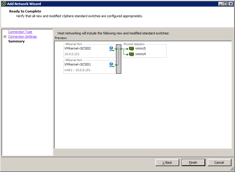
Click on: Finish
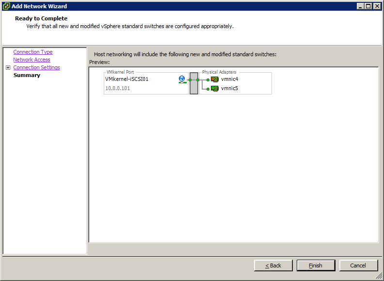
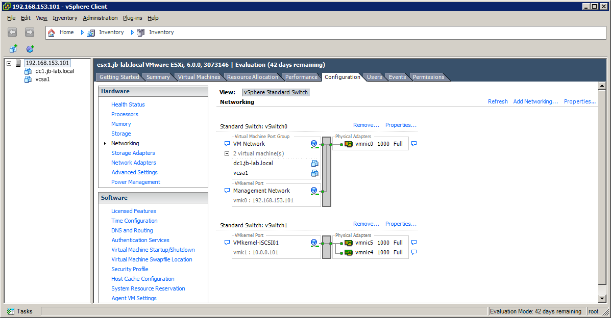
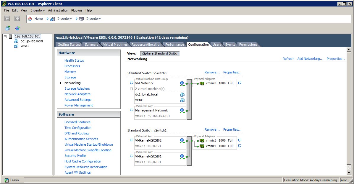
After you click: Finish, you will see the new vSwitch (in this case, vSwitch 1)
On vSwitch1, click: Properties (be careful, there are separate “Properties” dialogs for each vSwitch and the overall Networking as well!
Click: Add
Choose: VMkernel
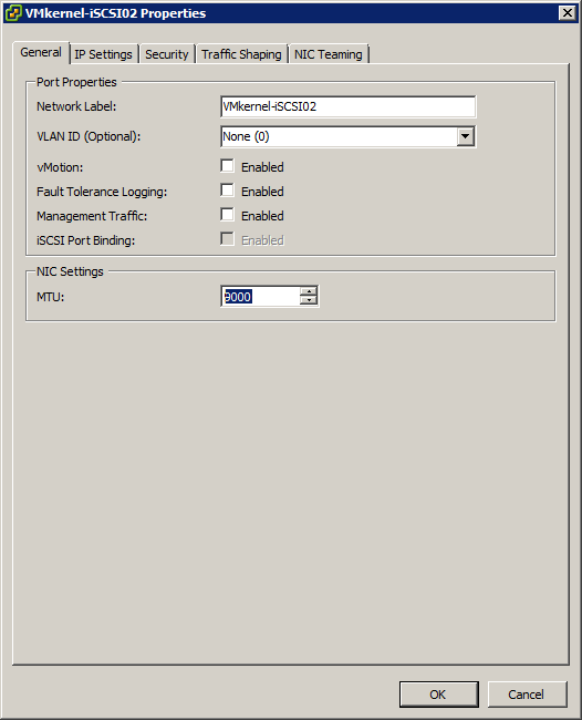
For the network label, choose a name that follows (sequentially) the VMkernel connection you created earlier.
Set a VLAN ID, if that is appropriate for your environment
Set an IP that follows the convention you established earlier. In my case, I am going to increment each VMkernel by 20.
Click: Finish
Repeat the previous steps for any additional iSCSI VMkernel connections you may be creating. You may only bind one iSCSI VMkernel per available uplink (vmnic)
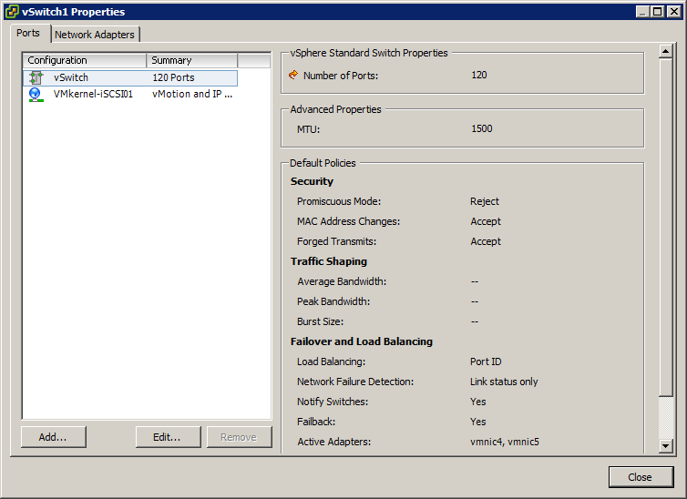
You will now find yourself on the Properties dialog for the vSwitch you created.
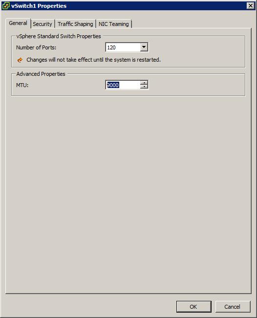
Highlight the vSwitch itself, and click: Edit
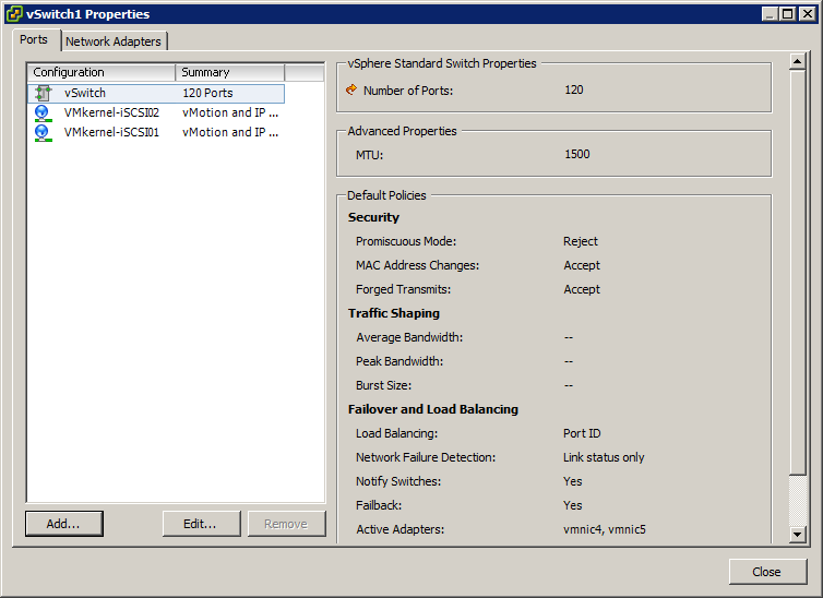
If you have chosen to use Jumbo Frames, set the MTU to 9000
Jumbo Frames MUST be configured on the vSwitch prior to setting the VMkernel MTU above 1500
Click: OK
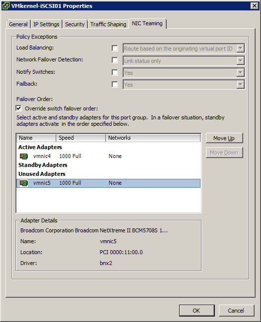
Now select the first (lowest numbered) iSCSI VMkernel and click: Edit

If you have chosen to use Jumbo Frames, set the MTU to 9000 and then go to the NIC Teaming Tab

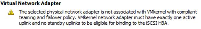
Our goal in this dialog is to remove all aspects of load-balancing and failover from the vSwitch in order to enable Port Binding. Port Binding will allow the vSphere Path Selection Policy (PSP) to more effectively balance iSCSI loads and implement failover in the event it is required.
In order implement Port Binding, we must leave only one active NIC
Choose: Override switch failover order
Since this is the lowest-numbered iSCSI VMkernel, we are going to give it the lowest-numbered vmnic, in this case vmnic4.
Highlight all other vmnic’s and click the Move Down button until they are all listed in Unused Adapters. Don’t be tempted to leave any NIC’s in Standby, it will not work, per VMware policy!
Click: OK
Now choose the next iSCSI VMkernel and choose: Edit

If you have chosen to use Jumbo Frames, set the MTU to 9000 and then go to the NIC Teaming Tab
Since this is the next iSCSI VMkernel, we are going to give it the next vmnic, in this case vmnic5.
Highlight all other vmnic’s and click the Move Down button until they are all listed in Unused Adapters. Don’t be tempted to leave any NIC’s in Standby, it will not work, per VMware policy!
Click: OK

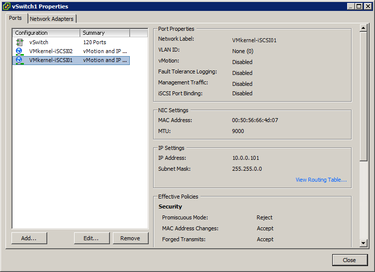
You may (it is a good idea to) check your settings by highlighting the vSwitch and each VMkernel in order and viewing the settings in the right-side column
Repeat the previous steps for any additional iSCSI VMkernel Connections you may have created and then click: close
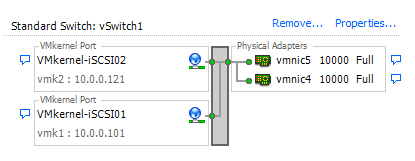
This is what the finished Standard vSwitch networking configuration should look like
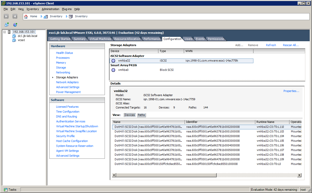
iSCSI Software Adapter
Choose: Storage Adapters and then click: Add
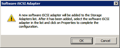
Choose: Add Software iSCSI Adapter
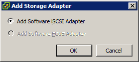
Click: OK
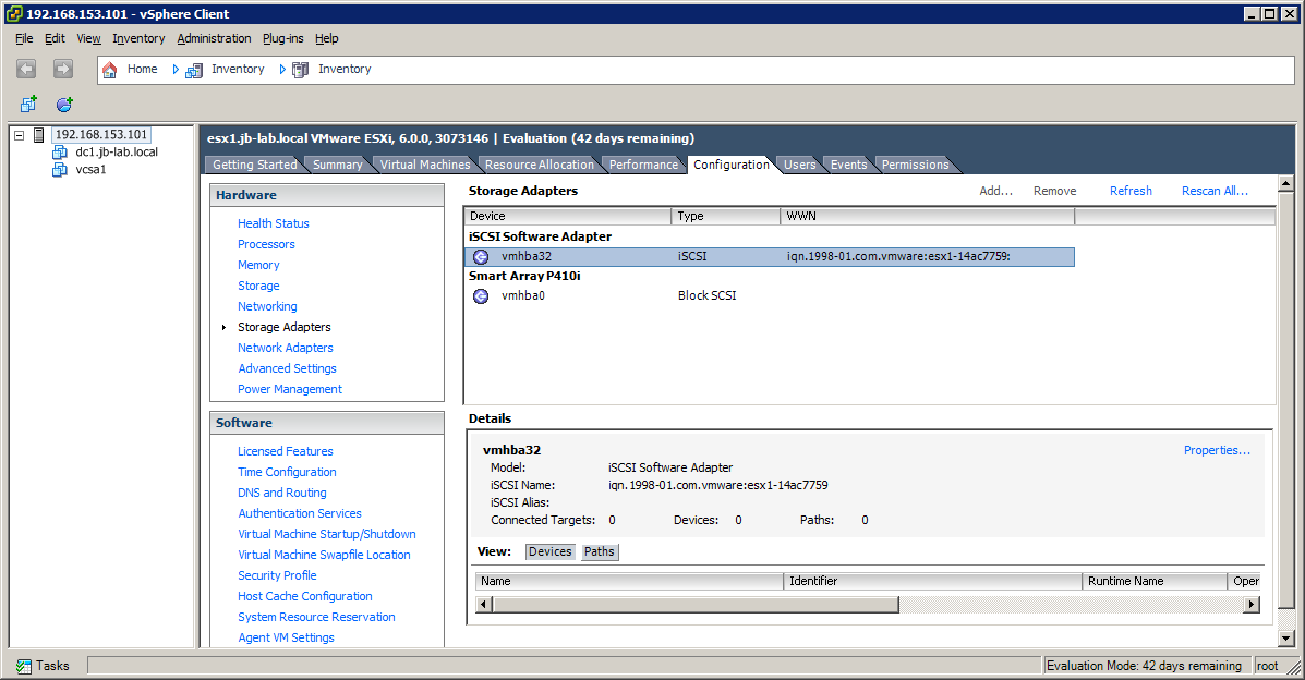
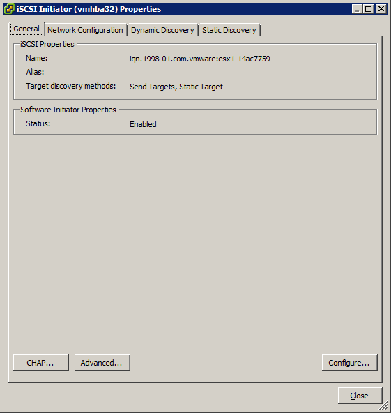
Right-click on the iSCSI Software Adapter and choose: Properties
Select the tab: Network Configuration
Click: Add
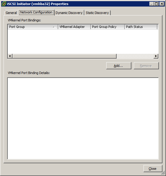
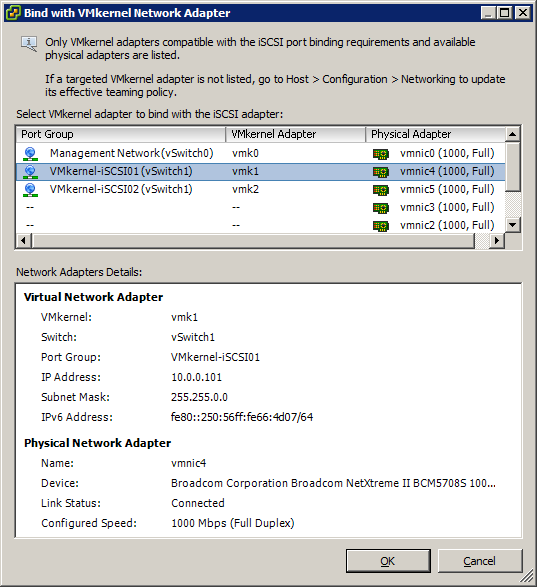
Choose one of the iSCSI VMkernel connections from the list and click: OK
Now click: Add

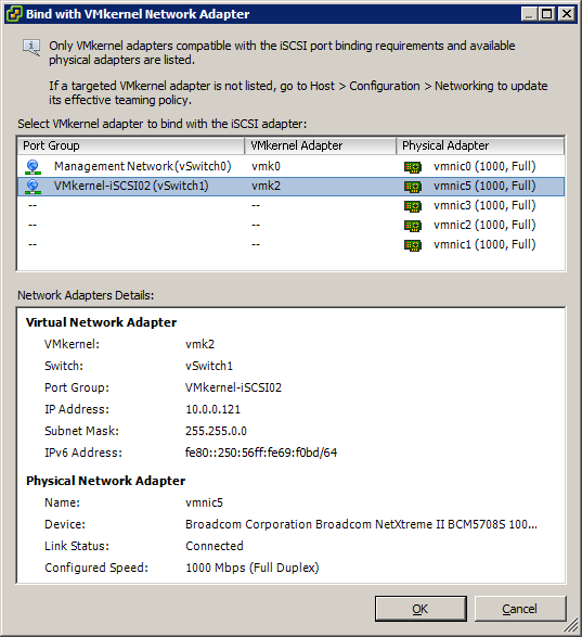
Choose the other iSCSI VMkernel connection and click: OK
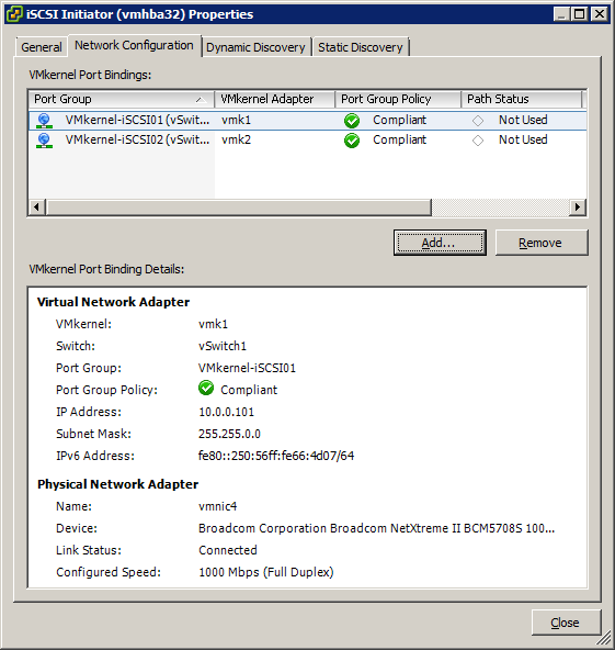
Repeat the previous process until all VMkernel iSCSI Connections are bound. DO NOT add Management Network connections, if they are available
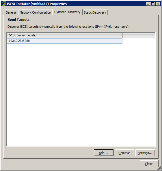
Choose the tab: Dynamic Discovery
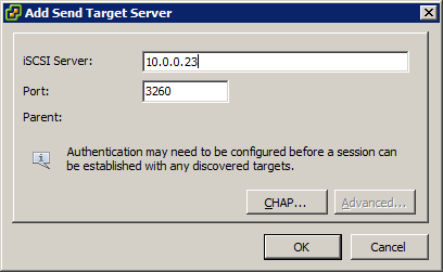
Click: Add
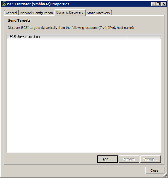
Enter the discovery IP of your SAN.
Enter just one address, one time.
Click: OK
The address will appear after some seconds.
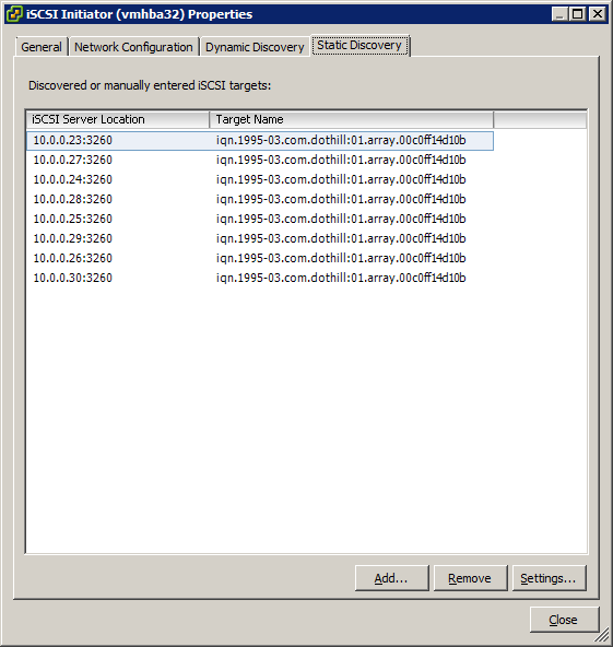
Click the Static Discovery tab and take note of how many paths, or targets your SAN presents (the more , the better!)
Click: Close
Click: OK
In a few seconds, you should see a listing of all of the devices (LUN’s) available on your SAN
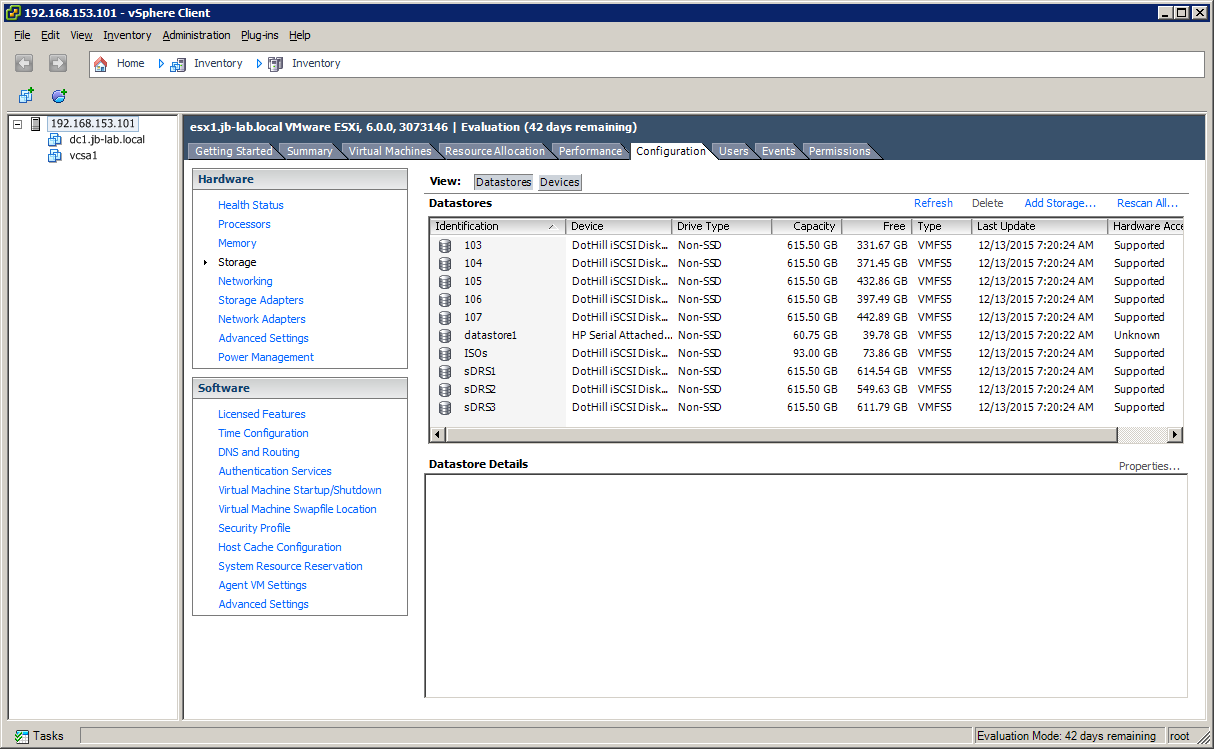
Creating a VMFS 5 Volume
Click on the option: Storage (middle column, in blue) and then click: Add Storage
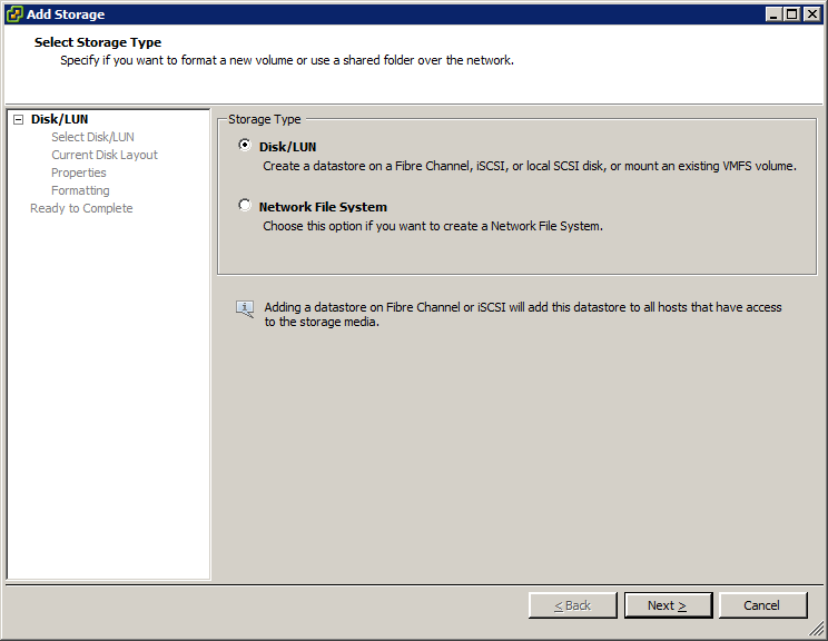
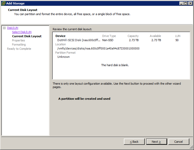
Choose: Disk/LUN and then: Next
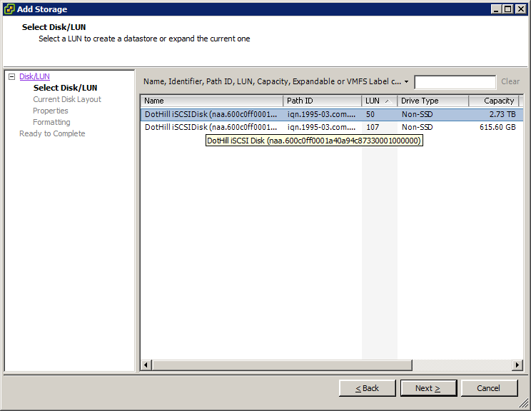
Choose from the available devices (LUN’s) and click: Next.
Click: Next
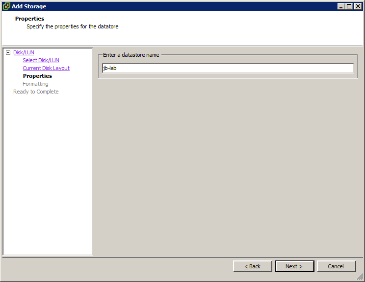
Name your Datastore and click: Next
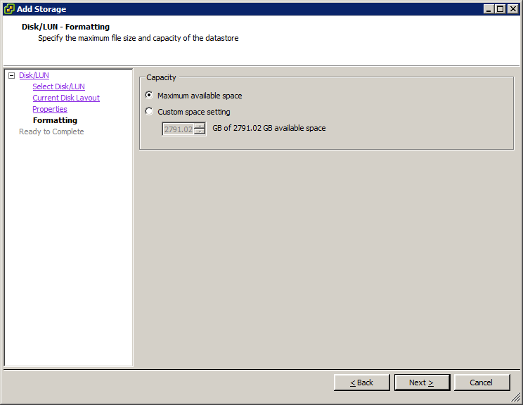
Choose: Maximum available space and click: Next
In reality, there is very little reason for choosing anything other than “Maximum available space”
Click: Next
Click: Finish
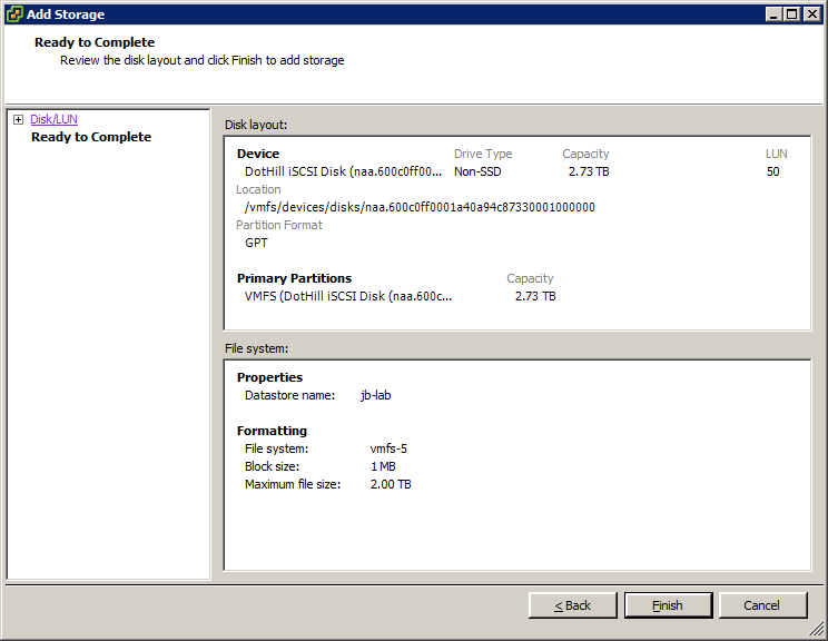
And your new VMFS 5 volume will be created!
- vSphere 6 Configuration Maximums ↑
- Multipathing Configuration for Software iSCSI Using Port Binding ↑